01
Application problem
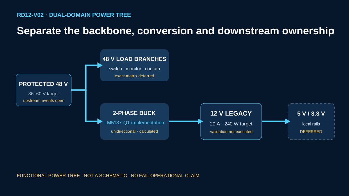
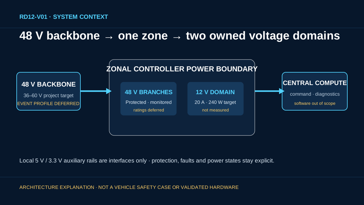
A 48 V vehicle backbone can reduce distribution current for higher-power loads, but a zone controller must also retain 12 V legacy loads and local low-voltage rails. RD12 defines who owns direct 48 V branches, 48 V-to-12 V conversion, downstream auxiliary rails, protection, faults and power states before selecting a controller. The page therefore begins with the vehicle-zone problem rather than LM5137-Q1.
- L1 application
- 48 V automotive zonal power architecture
- Local 48 V loads
- Direct protected branches; exact load classes deferred
- Retained 12 V loads
- 12 V / 20 A / 240 W project target
- Local auxiliary rails
- 5 V and 3.3 V interfaces; implementation deferred
02
System requirements
The continuous protected-input target is 36–60 V around a nominal 48 V backbone. The selected 12 V domain is unidirectional in RD12, with separate enable and protection ownership. Transient, reverse-energy, thermal, EMI and functional-safety requirements remain explicit open inputs rather than inferred capabilities.
| Requirement | Locked value | Evidence class | Boundary |
|---|---|---|---|
| Protected input | 36–60 V continuous; 48 V nominal | PROJECT_DESIGN_TARGET | OEM event profile deferred |
| 12 V domain | 12.0 V nominal · 20 A · 240 W | PROJECT_DESIGN_TARGET | Not measured |
| Conversion direction | 48 V to 12 V only | ARCHITECTURE_DECISION | Reverse power deferred |
| Switching target | 400 kHz per phase | PROJECT_DESIGN_TARGET | Tolerance and synchronization open |
| Efficiency objective | At least 94% at nominal input | PROJECT_DESIGN_TARGET | Must be evaluated on hardware |
| Fault containment | Independent protected branches by design intent | PROJECT_REQUIREMENT_UNVALIDATED | No fail-operational claim |
03
Architecture alternatives
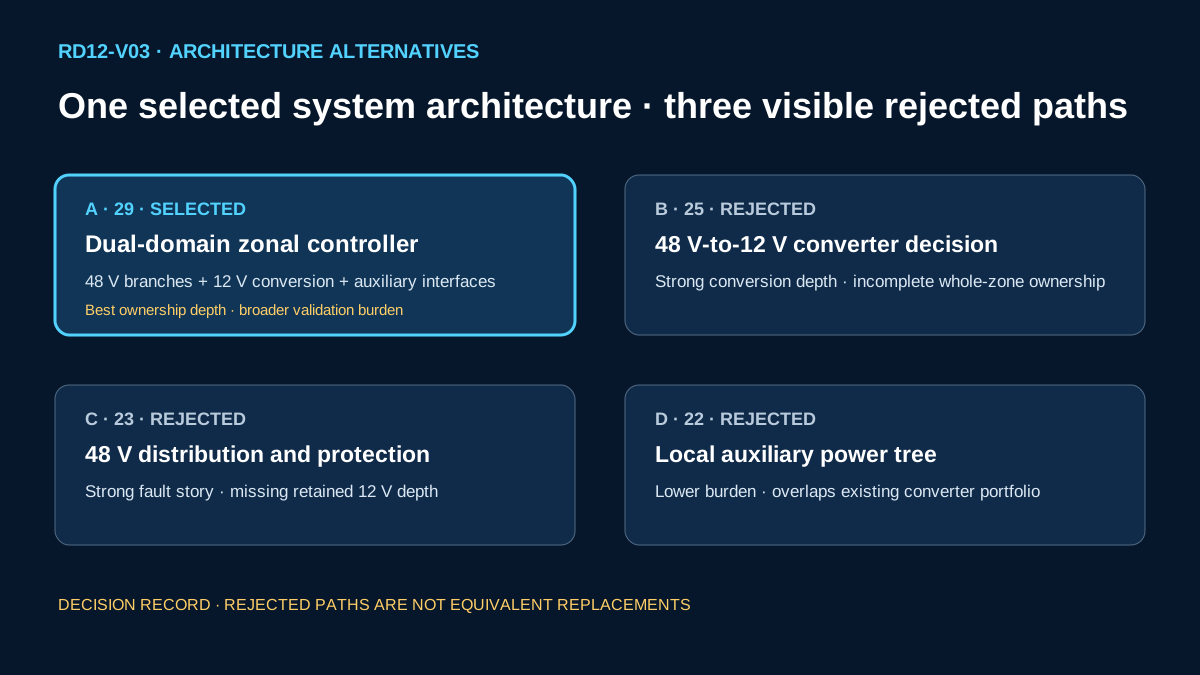
Four Stage A candidates were compared using application fit, portfolio gap, architecture depth, cross-vendor value, evidence, calculation tractability, visual clarity and PowerICDB relationship value, with overlap, complexity and claim-risk penalties. Rejected paths remain visible and are not described as equivalent replacements.
| Candidate | Architecture | Score | Trade-off | Decision |
|---|---|---|---|---|
| A | Dual-domain 48 V zonal controller architecture | 29 | Best system ownership and portfolio-depth fit; wider validation scope | SELECTED |
| B | 48 V-to-12 V zonal converter decision | 25 | More tractable conversion focus; weaker whole-zone ownership | REJECTED |
| C | 48 V zonal distribution and protection | 23 | Strong fault/harness story; conversion and auxiliary domains incomplete | REJECTED |
| D | Zone-controller local auxiliary power tree | 22 | Lower implementation burden; duplicates existing converter depth | REJECTED |
04
Why the selected architecture
Candidate A connects the 48 V backbone, local 48 V loads, the retained 12 V domain and future auxiliary rails in one reviewable ownership model. It also creates room for a vendor-neutral architecture decision while keeping the first implementation bounded to a unidirectional stage.
- WHAT VENDOR REFERENCE DESIGNS ALREADY DO — TI demonstrates a 48 V backbone and 48 V-to-12 V interface; Infineon covers integrated multiphase buck and switched-tank ecosystems; ST covers ZCU smart distribution and control context.
- WHAT HENGSHUN WILL NOT DUPLICATE — No vendor board, schematic, CAD, measured curve or block diagram is copied, and no vendor result is transferred to RD12.
- WHAT HENGSHUN ADDS — A traceable requirement-to-architecture decision, three-vendor non-equivalence matrix, reproducible project calculations, maturity-aware BOM, PowerICDB relationship plan and explicit unexecuted validation contract.
05
Cross-vendor component decision
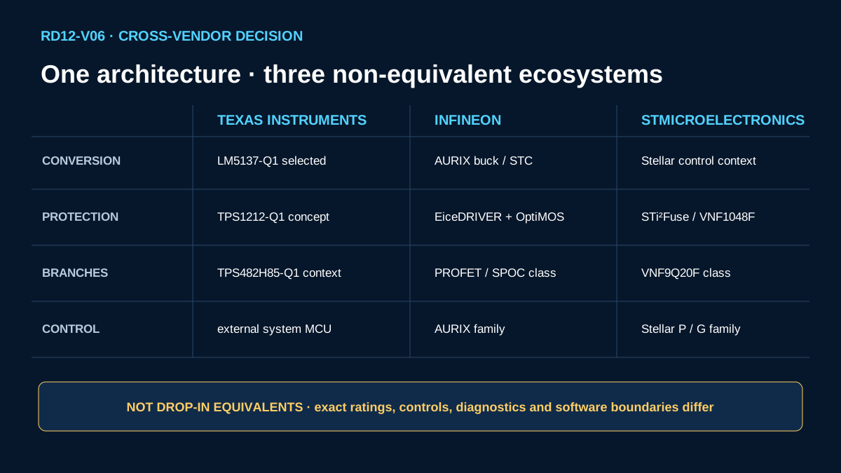
The architecture is vendor-neutral; the reference implementation is vendor-specific. Each alternative below occupies a reviewed functional class, but differences in integration, control, diagnostics, voltage, protection and software prevent drop-in-equivalence claims. These cross-vendor options are non-equivalent architecture alternatives, not replacement or equivalence claims.
| Functional block | Device class | TI | Infineon | ST | Decision / non-equivalence |
|---|---|---|---|---|---|
| 48 V backbone protection | External-FET smart high-side controller | TPS1212-Q1 | EiceDRIVER APD + OptiMOS 7 class | VNF1048F | TI primary; control and diagnostics differ |
| 48 V-to-12 V control | Multiphase synchronous buck control | LM5137-Q1 | AURIX-controlled buck/STC | Stellar-controlled ecosystem | TI primary; MCU paths add firmware and safety scope |
| Local low-power preregulation | Integrated preregulator | LM68645-Q1 | TLS5112C0EPV | ST 48 V-to-12 V portfolio | Context only; not the 240 W stage |
| Power switches | 80–100 V automotive MOSFET | Exact FET deferred | OptiMOS 7 class | STripFET F8 class | Cross-vendor screen; no selected equivalence |
| Protected branch switch | Smart high-side switch | TPS482H85-Q1 | PROFET/SPOC class | VNF9Q20F/STi2Fuse class | Ratings and protection curves differ |
| Zone control | Automotive MCU | External system MCU | AURIX family | Stellar P/G family | Outside primary power stage |
| Current measurement | Bidirectional current-sense amplifier | INA241A-Q1 | Automotive current-sense family | Automotive current-sense family | Exact common-mode and accuracy review required |
06
Selected reference implementation
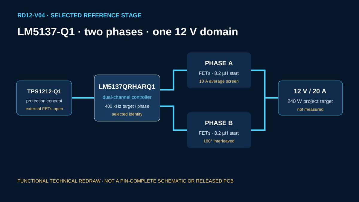
The selected implementation uses LM5137QRHARQ1 as a dual-channel controller configured for one two-phase interleaved synchronous buck. A separately protected 36–60 V node feeds the stage; two provisional 8.2 µH phase inductors supply the 12 V / 20 A target. TPS1212-Q1 represents the high-side protection-controller concept. This functional reference is not a pin-complete schematic or production netlist.
- Architecture
- Vendor-neutral dual-domain zone power
- Reference implementation
- TI-specific LM5137-Q1 dual-phase buck
- Selected orderable
- LM5137QRHARQ1
- Protection concept
- TPS1212-Q1 with external FETs
- Bidirectionality
- DEFERRED · not required by RD12
07
Engineering calculations
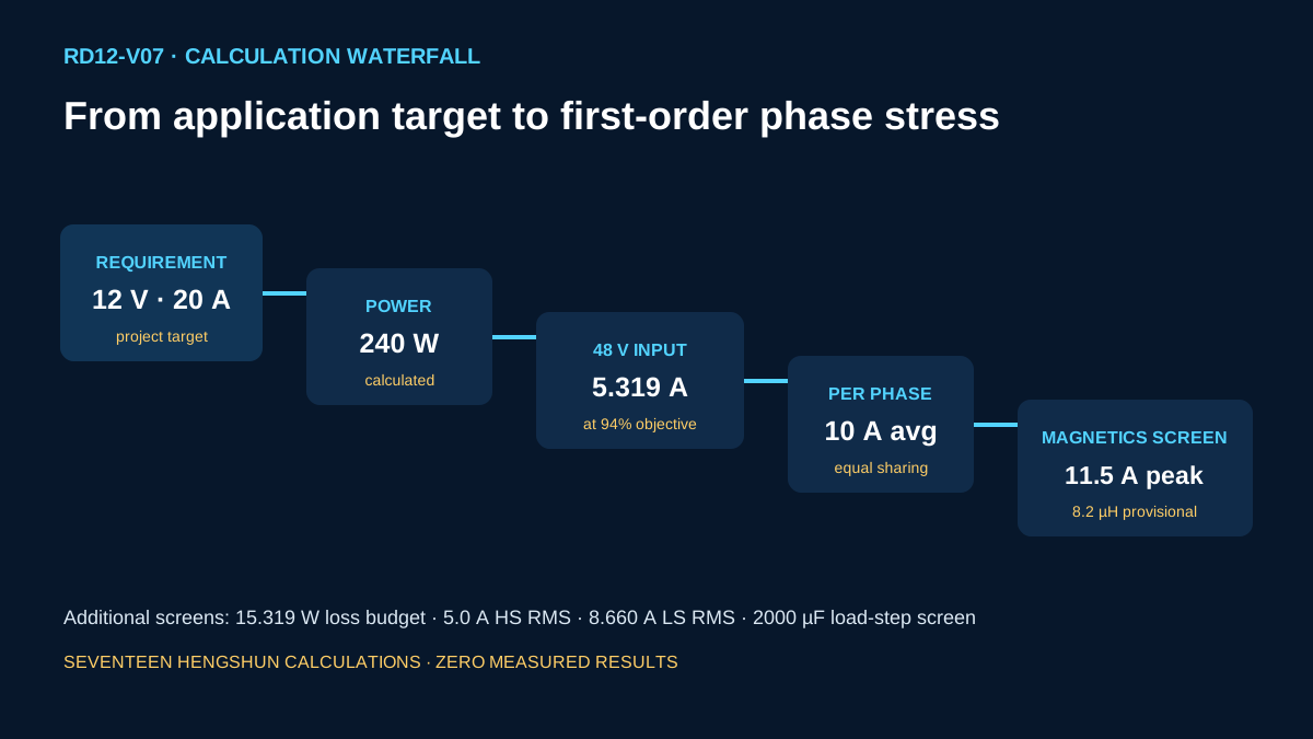
All seventeen rows are Hengshun first-order calculations copied from the Stage A lock. They use project targets and screening assumptions; none is a simulation, waveform or measured result.
| ID | Calculation | Equation and inputs | Result | Provenance / limit |
|---|---|---|---|---|
| C01 | Output power | Pout = 12 V × 20 A | 240 W | HENGSHUN_CALCULATION · target |
| C02 | Ideal nominal input current | Iin = 240 W / 48 V | 5 A | Loss excluded |
| C03 | Input current at objective | Iin = 240 / (48 × 0.94) | 5.319 A | 94% is a target |
| C04 | Loss budget | Ploss = 240 × (1 / 0.94 − 1) | 15.319 W | Lumped screen |
| C05 | Nominal duty | D = 12 / 48 | 0.25 ratio | Ideal |
| C06 | Low-line duty | D = 12 / 36 | 0.3333 ratio | Ideal |
| C07 | High-line duty | D = 12 / 60 | 0.20 ratio | Ideal |
| C08 | Per-phase average current | Iphase = 20 / 2 | 10 A | Equal sharing assumed |
| C09 | Nominal inductance | L = (48−12) × 0.25 / (3 × 400 kHz) | 7.5 µH | 3 A ripple target |
| C10 | High-line inductance | L = (60−12) × 0.20 / (3 × 400 kHz) | 8.0 µH | Ideal endpoint |
| C11 | Per-phase peak current | Ipk = 10 + 3 / 2 | 11.5 A | Transient overshoot excluded |
| C12 | High-side RMS current | Ihs = 10 × sqrt(0.25) | 5.0 A | Ripple excluded |
| C13 | Low-side RMS current | Ils = 10 × sqrt(0.75) | 8.660 A | Dead time excluded |
| C14 | High-side conduction example | P = 5² × 0.005 | 0.125 W per device | 5 mΩ screening assumption |
| C15 | Low-side conduction example | P = 8.660² × 0.005 | 0.375 W per device | Temperature dependence excluded |
| C16 | Load-step capacitance | C = 10 A × 100 µs / 0.5 V | 0.002 F | ESR, ESL and loop response excluded |
| C17 | Equal-power current ratio | I48 / I12 = 12 / 48 | 0.25 ratio | Converter loss excluded |
08
Protection and fault ownership
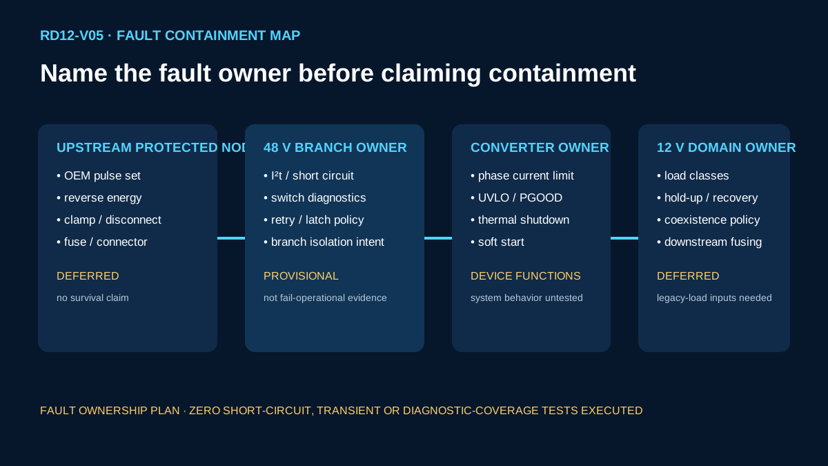
Vehicle-level events terminate at an upstream protected 48 V node whose TVS, reverse-energy path, disconnect FETs, fuse and connector are deferred. TPS1212-Q1 controls an external-FET high-side concept and exposes monitoring and protection functions, but exact thresholds, I2t, SOA, retry and latch policy require the final branch matrix. The converter owns regulated-stage current limiting; it does not close the vehicle safety case.
Unvalidated fault boundary
- Independent-branch fault containment is a project requirement, not a demonstrated fail-operational result.
- No short-circuit, overload, reverse-energy, transient-survival or diagnostic-coverage test has been executed.
- Functional-safety goals and ASIL allocation remain with the system safety process.
09
Power-state, always-on and switched-domain behavior
The backbone protection controller, the 48 V branch switches and the 48 V-to-12 V converter require separate control ownership. The selected design intends an independently controllable 12 V domain, switched 48 V branches and a future low-power wake path. Wake source, MCU rail, standby budget, sequencing, 12 V battery coexistence and safe-state behavior remain deferred and must not be inferred from individual IC low-power modes.
- Always-on ownership
- DEFERRED to system wake and safety contract
- 12 V converter enable
- Separately controllable architecture requirement
- 48 V branches
- Individually switched/monitored by design intent
- Measured standby current
- NOT COLLECTED
10
Critical BOM maturity
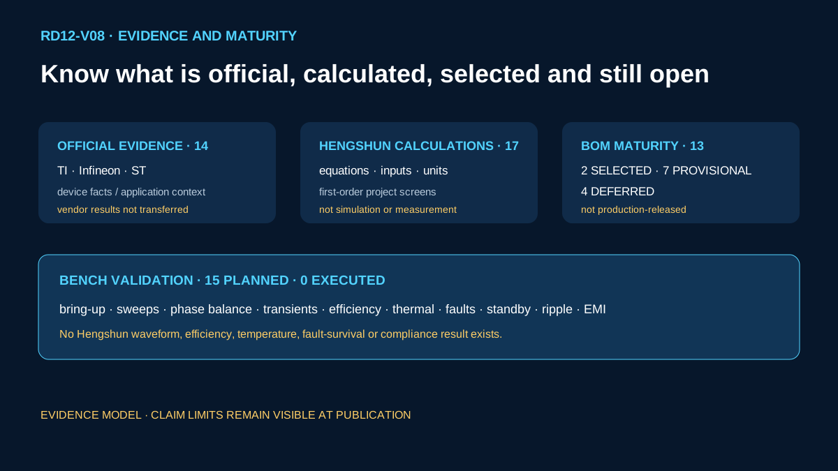
The Stage A split is preserved exactly: two selected rows, seven provisional rows and four deferred rows. Selected fixes the controller identities only; it does not release the complete converter, protection system or supply chain.
| ID | Function | Candidate | Status | Next evidence gate |
|---|---|---|---|---|
| B01 | Multiphase buck controller | LM5137QRHARQ1 | SELECTED | Exact controller networks and loop design |
| B02 | 48 V high-side protection controller | TPS1212-Q1 | SELECTED | Exact orderable and event/SOA coordination |
| B03 | Phase inductors | 8.2 µH shielded automotive parts | PROVISIONAL | AEC-Q200, saturation, loss, DCR and thermal |
| B04 | High-side MOSFETs | 80 V or 100 V automotive N-channel | PROVISIONAL | RDS(on), Qg, SOA, avalanche and thermal |
| B05 | Low-side MOSFETs | 80 V automotive N-channel | PROVISIONAL | Loss and thermal optimization |
| B06 | Current-sense element | Low-ohm automotive shunt | PROVISIONAL | Pulse power, tolerance and Kelvin layout |
| B07 | Input capacitor bank | 63 V-or-higher polymer plus ceramic | PROVISIONAL | Derating, ripple, impedance and event coordination |
| B08 | Output capacitor bank | 12 V-domain polymer plus ceramic | PROVISIONAL | ESR, ESL, transient response and loop stability |
| B09 | Gate-drive support | Controller bias and bootstrap network | PROVISIONAL | Datasheet/EVM network review |
| B10 | EMI input filter | Differential/common-mode network | DEFERRED | Harness, LISN, class and damping study |
| B11 | 48 V branch switches | Exact smart-switch matrix TBD | DEFERRED | Load classes and protection curves |
| B12 | Zone-control MCU | AURIX, Stellar or system MCU | DEFERRED | Safety, software and diagnostics ownership |
| B13 | Event clamp/reverse-energy path | Vehicle-rated network TBD | DEFERRED | OEM pulse set, energy and SOA closure |
11
Validation plan
The Stage A plan contains fifteen future bench items and zero executed items. Every line is work to be performed later under approved fixtures and acceptance criteria; none is a pass result or evidence of measured performance.
- PLANNED_NOT_EXECUTED — BP01 Pre-power inspection: verify polarity, assembly identity, resistance and continuity before energization.
- PLANNED_NOT_EXECUTED — BP02 Current-limited bring-up: observe the 12 V rail, input current, enable, startup and PGOOD from a programmable 36–60 V source.
- PLANNED_NOT_EXECUTED — BP03 Input sweep: exercise 36–60 V at representative 10%, 50% and 100% loads; the final 12 V tolerance remains to be locked.
- PLANNED_NOT_EXECUTED — BP04 Load sweep: exercise 0–20 A at 36 V, 48 V and 60 V while observing regulation, phase current and protection state.
- PLANNED_NOT_EXECUTED — BP05 Phase-current balance: capture average, peak and RMS current in both phases across the operating matrix.
- PLANNED_NOT_EXECUTED — BP06 Load transient: apply defined 5–15 A and 10–20 A steps; the 0.5 V deviation is an initial screen, not an acceptance result.
- PLANNED_NOT_EXECUTED — BP07 Line transient: apply bounded 36 V, 48 V and 60 V transitions and observe regulation and false-trip behavior.
- PLANNED_NOT_EXECUTED — BP08 Efficiency map: use calibrated source and load instrumentation to evaluate, rather than assume, the 94% objective.
- PLANNED_NOT_EXECUTED — BP09 Thermal characterization: measure controller, MOSFET, inductor, capacitor and connector temperatures after the mechanical boundary is locked.
- PLANNED_NOT_EXECUTED — BP10 Short-circuit and overload: execute only under an approved safety procedure after component SOA closure.
- PLANNED_NOT_EXECUTED — BP11 48 V branch isolation: inject a representative branch fault and observe unrelated protected branches and diagnostics.
- PLANNED_NOT_EXECUTED — BP12 Standby and wake: measure shutdown, standby, wake timing and inrush for defined control states.
- PLANNED_NOT_EXECUTED — BP13 Output ripple: measure with a declared bandwidth and low-inductance probe fixture.
- PLANNED_NOT_EXECUTED — BP14 Conducted EMI pre-scan: engineering discovery only after the LISN, harness and program class are defined.
- PLANNED_NOT_EXECUTED — BP15 Protected-node event testing: execute only after the OEM pulse set, clamp network and SOA review are approved.
12
Evidence maturity and claim limits
RD12 keeps six product-model layers visible: application requirement, architecture decision, cross-vendor decision, selected implementation, evidence/validation maturity and PowerICDB relationship. Official sources establish vendor facts or application context; targets and calculations remain Hengshun work; validation remains unexecuted.
| Label | Meaning | RD12 use |
|---|---|---|
| OFFICIAL_DEVICE_FACT | Vendor-published device identity or capability | Attributed; not a system result |
| OFFICIAL_APPLICATION_CONTEXT | Vendor application or reference context | No board or result transfer |
| PROJECT_DESIGN_TARGET | Hengshun requirement awaiting validation | 36–60 V, 12 V / 20 A, 94% objective |
| HENGSHUN_CALCULATION | Reproducible first-order calculation | Seventeen rows; not measured |
| SELECTED | Identity locked for the candidate | Two controller rows |
| PROVISIONAL | Starting point requiring evidence | Seven BOM rows |
| DEFERRED | Blocked on later system input | Four BOM rows |
| PLANNED_NOT_EXECUTED | Future validation work | Fifteen items; zero executed |
| VENDOR_MEASURED_CONTEXT | Vendor result under vendor conditions | Not represented as Hengshun evidence |
13
Official sources
Fourteen Stage A sources from Texas Instruments, Infineon and STMicroelectronics form the factual boundary. Product pages govern device facts; application and reference pages provide vendor context only. No nonofficial source is used for a primary claim.
14
Related Hengshun engineering pages
Use the existing wide-input converter, always-on rail, automotive buck, protection solution and technical guides to move from system architecture into narrower implementation questions. Request a Design carries the unresolved load, event, thermal, EMI and power-state requirements into an engineering discussion.
15
PowerICDB component links where available
The Stage A relationship plan has ten entries. No matching reviewed LM5137-Q1 or TPS1212-Q1 Product Detail is currently asserted, so device relationships remain explicit planned or discovery states rather than invented links. Existing Hengshun solution, application, reference-design, guide and Request a Design links use the current relationship system.
| ID | Block | Target | Status | Rule |
|---|---|---|---|---|
| R01 | Primary converter | LM5137-Q1 Product Detail | PLANNED_NO_LINK | Use exact reviewed record only if available |
| R02 | Backbone protection | TPS1212-Q1 Product Detail | PLANNED_NO_LINK | Do not imply complete branch qualification |
| R03 | 48 V smart branch | TPS482H85-Q1 | DISCOVERY_ONLY | Context alternative, not BOM substitute |
| R04 | Current measurement | INA241A-Q1 | DISCOVERY_ONLY | Exact common-mode review required |
| R05 | Local preregulation | TLS5112C0EPV | PLANNED_NO_LINK | Not the 240 W converter |
| R06 | Power switches | 80 V automotive MOSFET family | DISCOVERY_ONLY | No automatic selection |
| R07 | Smart distribution | STi2Fuse family | DISCOVERY_ONLY | Technology context only |
| R08 | Zone control | AURIX and Stellar | DEFERRED | Outside primary power stage |
| R09 | Reference design | DC-DC converter solution family | RESOLVED_LINK | Application-first journey |
| R10 | Conversion | Request a Design | RESOLVED_LINK | Non-sensitive requirements only |