01
I know the application
Start with the system context—BMS, ECU, ADAS, infotainment or industrial control—and identify the power questions that matter there.
BMS · ECU · ADAS · Industrial control
Explore applicationsPower electronics design guidance
Start from your application, electrical requirement, known component or design question. Hengshun connects each starting point to relevant power solutions, component guidance, technical resources and engineering support.
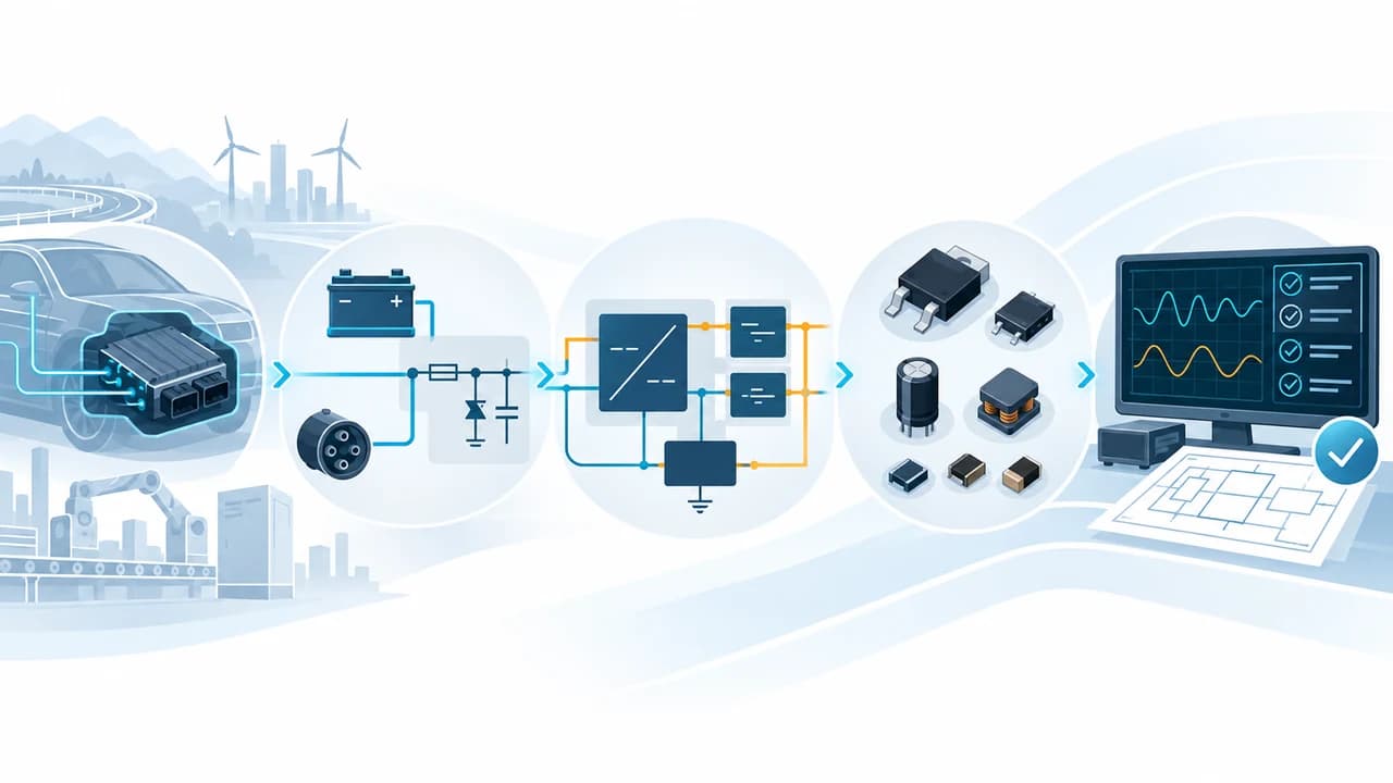
Application or requirement → architecture → component decisions → engineering support
Choose your starting point
Use the information you already have. You do not need a finished specification to find a useful path through the site.
Start with the system context—BMS, ECU, ADAS, infotainment or industrial control—and identify the power questions that matter there.
BMS · ECU · ADAS · Industrial control
Explore applicationsStart with the conversion or management need, then review suitable architectures, operating limits and design trade-offs.
12 V to 5 V · 24 V auxiliary · 48 V step-down
Explore solutionsUse a reviewed component guide to understand where the device fits and what still needs to be checked in the complete design.
TPS54260-Q1 · LM5161-Q1 · LM76002-Q1
Browse component guidesShare an incomplete requirement or a specific design question so the next engineering decision can be scoped clearly.
Architecture · selection · review planning
Request a designHow Hengshun works
Use Hengshun as a guided path rather than a document library. Each step narrows the question and makes the next decision more concrete.
Common design paths
These examples use only currently published applications, solutions, component guides and technical guides.
Journey 01
Move from the BMS operating context to conversion architecture, a calculated reference design and the selected regulator guidance.
Journey 02
Connect the industrial or zone-controller environment with wide-input architecture and verified component-selection questions.
Journey 03
Start from a part number, then check its application fit, related solution context and the engineering guidance needed for a decision.
Follow this pathFour main content entries
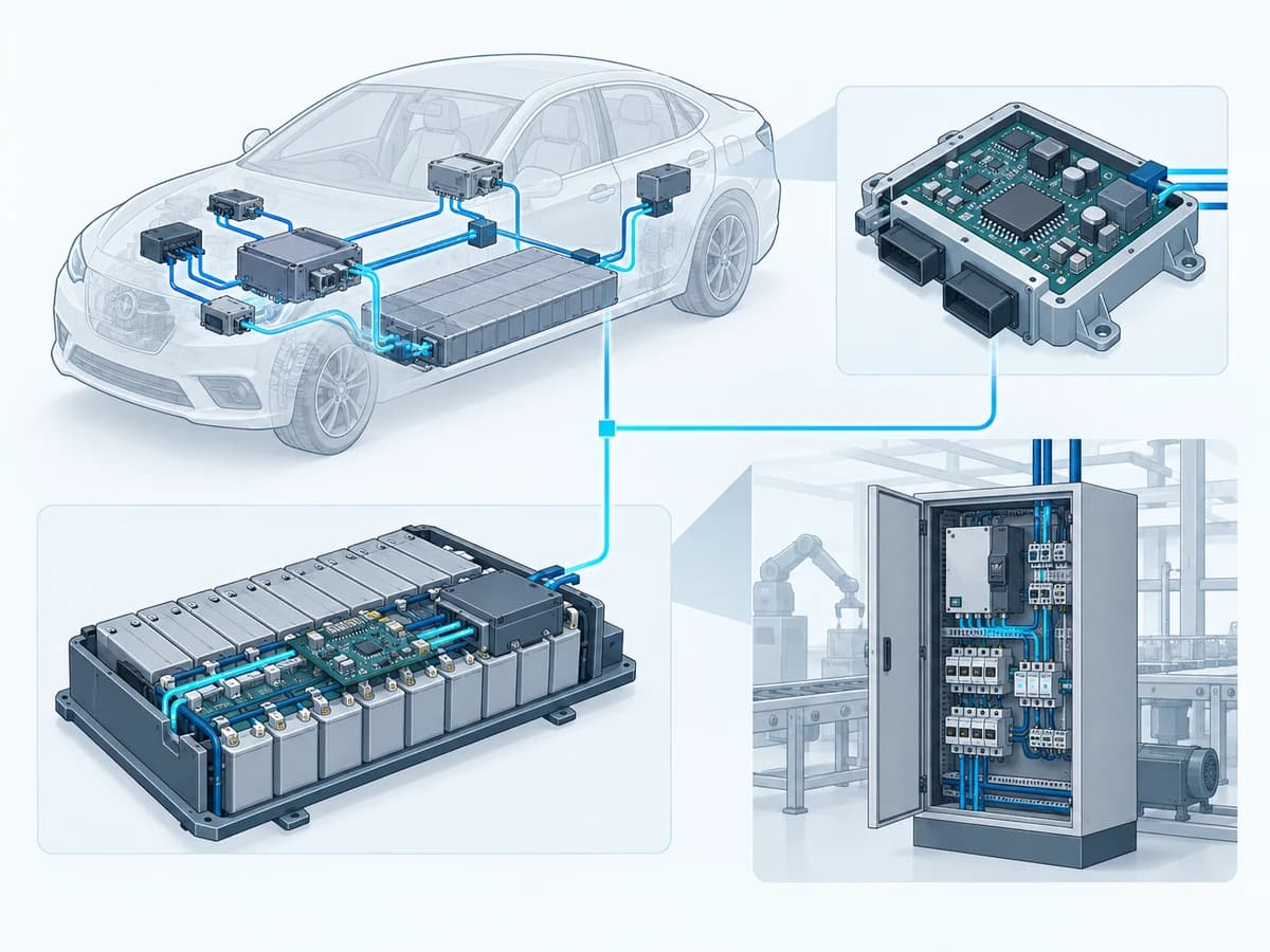
Applications
See the power-design topics most relevant to the operating environment, loads, states and fault behavior of the application.
Explore Applications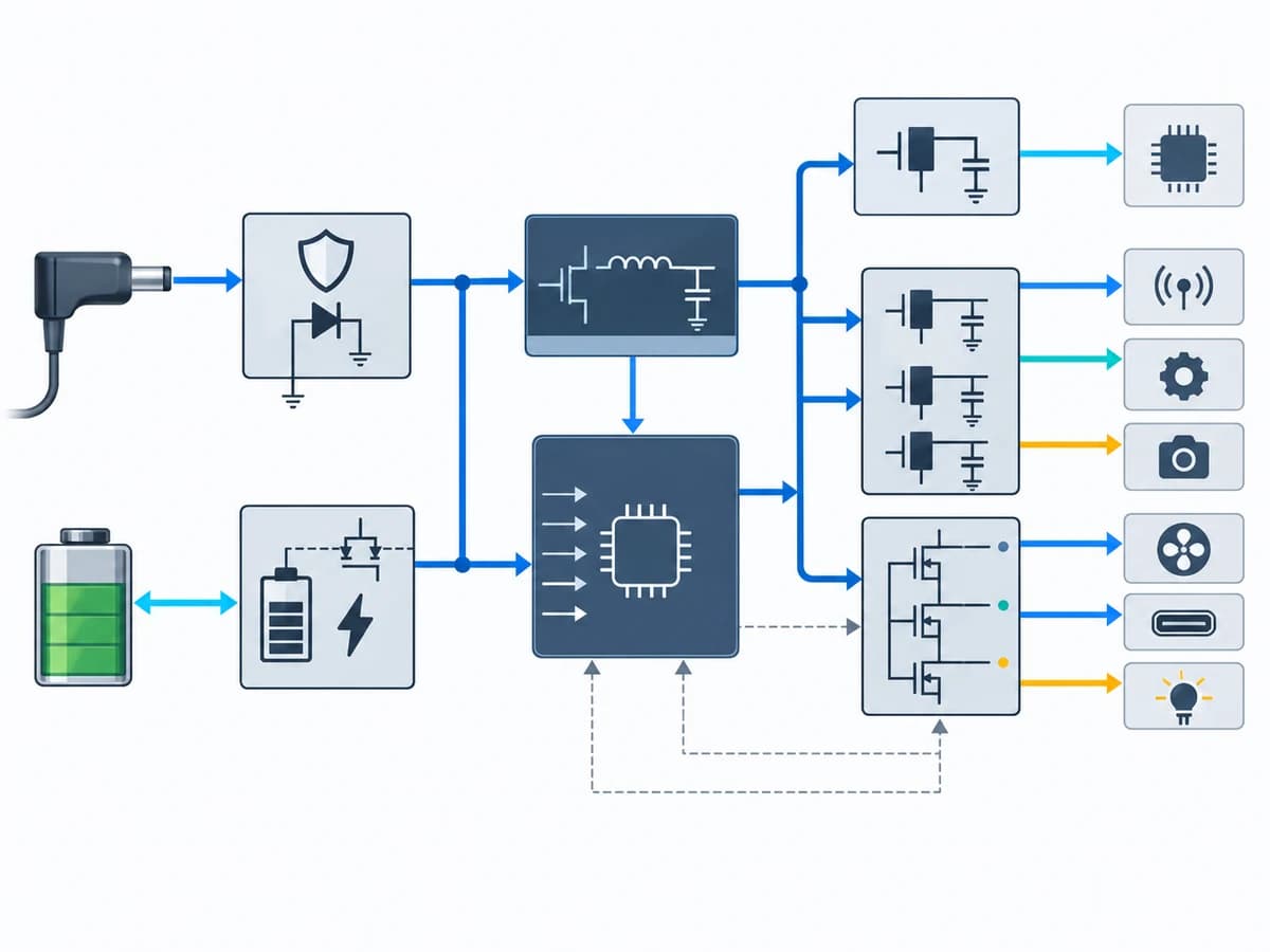
Solutions
Review the architecture and engineering considerations behind conversion, regulation, protection, charging and distribution.
Explore Solutions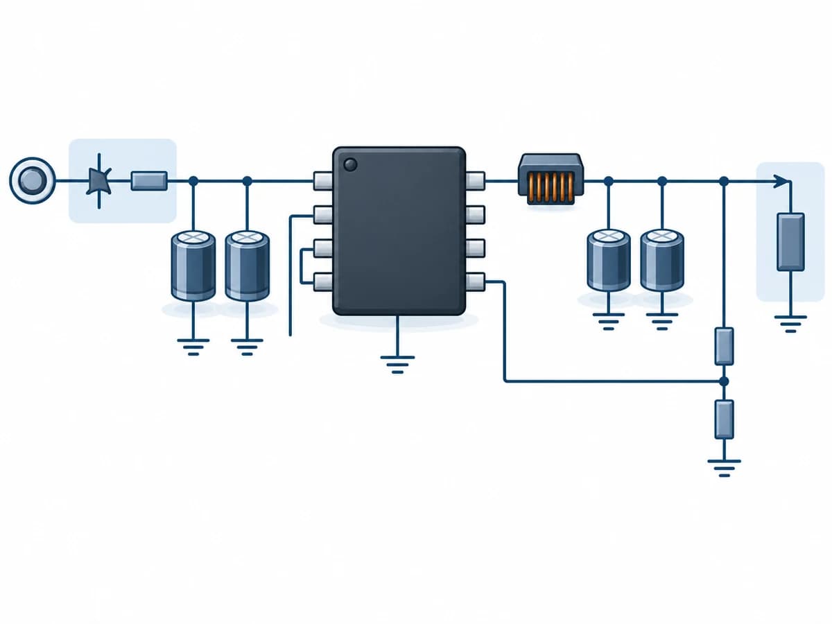
Component Guides
Review where the device fits, the design questions it raises and the related application and solution context.
Browse Component Guides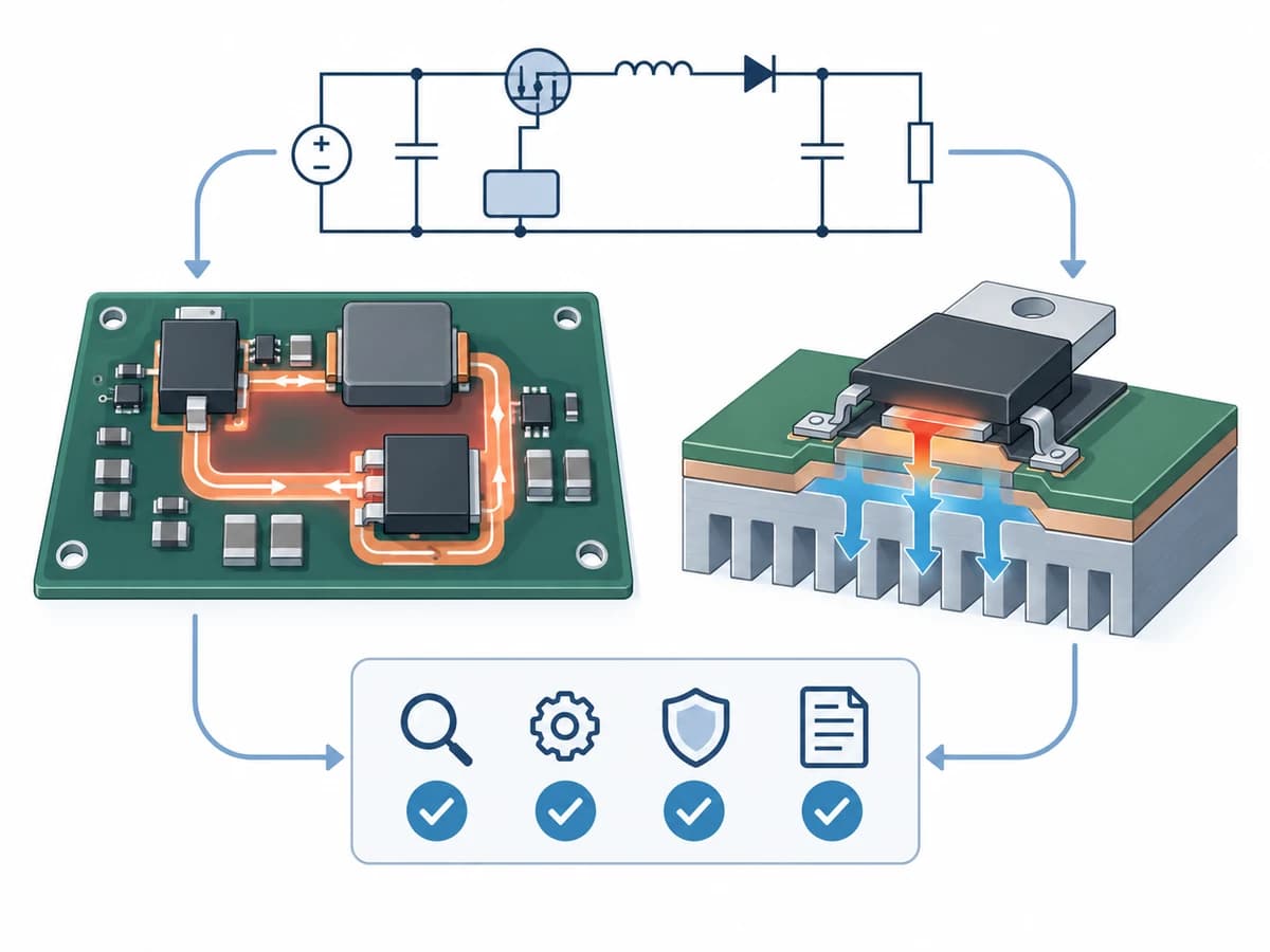
Technical Guides
Review practical design principles, trade-offs, protection questions and validation considerations.
Read Technical GuidesFeatured reviewed resources
Reviewed component design guides are now available for selected parts; additional guides remain in preparation. Reviewed component and technical guides are available now, with additional engineering resources being expanded progressively. The current collection includes 12 calculated reference designs, 8 component guides and three technical guides.
Calculated reference design
Calculated automotive power reference design for a protected 6–28 V input and a 5 V / 3 A output using LM61440-Q1. It publishes the locked power-stage and front-end calculations while keeping capacitor derating, transient dynamics, thermal, EMI and bench evidence explicitly open.
Calculated reference design
Calculated engineering publication candidate for a protected 24 V industrial input and a 5 V / 3 A output using LM76003RNPT. It records the locked input boundary, power-stage calculations, explicit BOM maturity and an unexecuted validation plan without making a board, surge, thermal, EMI or compliance claim.
Calculated reference design
Calculated synchronous buck reference design for a 36–60 V continuous input and a 12 V / 1 A output using LMR38020-Q1. It publishes the power-stage calculations and BOM maturity while keeping front-end protection explicitly provisional.
Calculated reference design
Calculated LM5164-Q1 always-on automotive buck reference design for a protected 6–36 V node and a 3.3 V / 300 mA keep-alive rail, with device-IQ context, explicit calculation provenance and fifteen planned, unexecuted validation items.
Calculated reference design
Application-first architecture for a protected 48 V vehicle backbone that keeps local 48 V loads, retained 12 V legacy loads and low-voltage auxiliary rails under explicit protection, fault and power-state ownership.
Calculated reference design
Calculated reference design for a protected 7–36 V input synchronous buck stage using LM5161-Q1 to produce a 5 V / 1 A BMS auxiliary rail. It separates raw battery events from protected VIN, shows the selected values and margins, and identifies the simulation, prototype and compliance evidence that is still required.
Calculated reference design
Calculated reference design for a protected 12 V automotive source feeding a 5 V / 0.65 A LM65625-Q1 buck stage and a 3.3 V / 0.40 A LM1117-Q1 rail. The architecture, calculations and BOM maturity are documented; board, thermal, EMI, noise, PSRR and camera-module validation have not been executed.
Calculated reference design
Calculated primary-side-regulated isolated flyback publication candidate for a protected 20–60 V industrial source and a 16.4 V / 0.9 A / 14.76 W auxiliary output using LM5185QPWPRQ1. It preserves the official 20–60 V, 16.4 V / 1 A TI EVM as reference evidence while keeping the Hengshun target, BOM maturity and thirteen unexecuted validation gates explicit.
Calculated reference design
Calculated UCC14240-Q1 isolated gate-driver bias publication candidate for a protected 24 V auxiliary rail. It converts the official 21–27 V normal input range into +15 V and -5 V rails for a calculated 1.25 W load while keeping the project-defined 30 V protected-node event, basic-isolation boundary, provisional passives and unexecuted validation work explicit.
Calculated reference design
Calculated TPSM8D6C24 high-current point-of-load publication candidate for industrial FPGA and ASIC compute. One two-phase module converts a protected 5–16 V intermediate bus to a 0.8 V / 70 A design target while keeping thermal derating, copper and interconnect design, capacitor selection, PMBus configuration and all physical validation explicitly open.
Calculated reference design
Calculated LM5155-Q1 non-synchronous boost reference design for a protected 6–18 V automotive input and 24 V / 2 A output, with explicit component maturity and unexecuted validation boundaries.
Calculated reference design
Calculated BQ25798 four-switch buck-boost charger reference design for a 5–20 V source, a 2S Li-ion pack and an NVDC system rail, with source-limited low-line behavior and explicit evidence boundaries.
A requirements-led framework for selecting an automotive buck converter. The guide connects the vehicle input envelope and load profile with conversion ratio, operating mode, magnetics, thermal limits, EMI layout, protection, qualification evidence and supply-lifecycle review.
Explore 02 /An engineering framework for defining automotive power-input conditions beyond nominal battery voltage. It organizes supply states, transient categories, reverse polarity, front-end protection, regulator survivability, energy handling, layout and validation without asserting compliance to an unspecified standard.
Explore 03 /A practical design framework for non-isolated wide-input DC-DC conversion in 24 V and 48 V systems. It covers source-envelope definition, topology boundaries, device-voltage margin, high-ratio switching, magnetics, thermal and EMI decisions, protection and validation.
ExploreEngineering support
Share the application, input and output requirements, power level, operating environment and project questions. Hengshun can use that context to guide the next engineering step.